Mason Caradice Design


Modelling & Testing


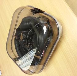
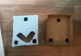
At first i drew out a net of the case onto card the size the actual case would be, i then cut it out and glued it together. After this i placed the headphone into the cardboard tray i created. The headphones fit in perfect with around 5-10mm clearence all the way around the headphones. This shows that the headphone will fit perfectly into the final product.
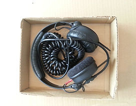
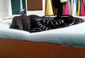
From the box model it was apparent that the headphone would move around in the case while in transit. To over come this i had to think of something that would stop this in order for the headphones to be protected even more. The idea i can up with was a foam insert which allows the headphone to be fixed into a safe position but still be easily removed. I drew the outline of the headphones onto a sheet of foam and cut it out. I then cut a squar around the headphones shape in order for the foam to go into the box. I placed the headphone into the cut out area but the headphones where still not fully in place as the cups of the headphones are alot bigger than the head band/piece as shown in the images below and above.
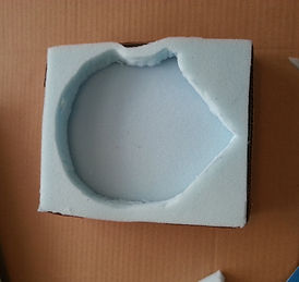
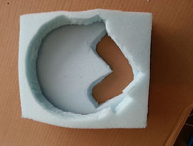
With an added bit of foam added to the underneith the same proble occured so i cut out a shape where the cups would fall and sit into. In this model the shape is cut all the way through but on the final one there will be around 3mm of foam still uncut for a fully foam base for the headphone to sit onto for full protection. I could not do this as the tools and equiptment i had would not enable me to leave some foam on the bottom.
With an added bit of foam added to the underneith the same proble occured so i cut out a shape where the cups would fall and sit into. In this model the shape is cut all the way through but on the final one there will be around 3mm of foam still uncut for a fully foam base for the headphone to sit onto for full protection. I also left the midle out as this enables the user to place the wires there. I also added velcro tabs on both the bottom of the foam and cardboard box as on the final product the foam willl be interchangeable if you get new headphone or use the case for the type you want to wear on the day. This alos allows for more room in the cases for any added extras that they may want to protect but taking the foam out reduces protection but the case itself so protect it more than most others anyway.


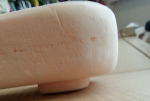

Aswell as modelling the legs out in CAD i also did a physical model from foam board. I did this as it gave me a better understanding of the scale the legs should be in order to look right. The first legs i modelled were approximatly 12mm in height. These legs were to big and did not look right. I then took 7mm off these so they were 5mm in height these still looked like they didnt fit in for the type of product it is. This then made me look into a couple of smaller designs that could be on the product.


The original plan was to use small black plastic ratchet rivets instead of metal ones as this would give to product a better looking finish. i Started off by sourcing some scrap 3mm polycarbonate. I then drilled a 3mm hole for the rivets to go through into the polycarbonate. I then attached a length of 15mm webbing to the polycarbonate with a ratchet rivet. I then tested to see if the rivets were strong enough by pulling the webbing. Low and behold the rivets were not strong enough leaving me one option which was to use metal rivets as i knew these would be strong enough to hold the product together.


When the tools finished on the cnc router i then had to drill holes around the tool and in the lettering in order for the vacuum to suck the material around the tools when its being formed. After this i then attached the tools to a piece of mdf so that it could be placed and attached into the vacuum former to start forming the shells.

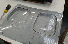
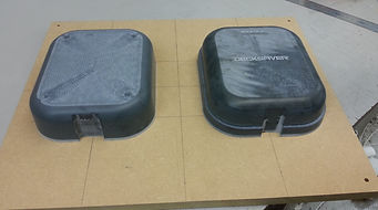
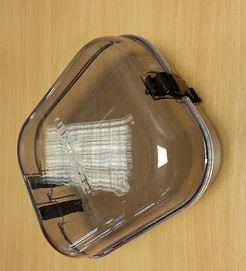
The tools where then placed into the vacuum former. The above picturedr shows the plastic beig formed around the tools. I then took the formed sheet from the vacuum former. The picture abobve and right was the first forming it did not form properly at the base of the tool so i we had to try again but with more and longer heat applied. The second forming was spot on apart from the "Made in the uk" text which did not come out the best.

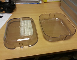

I then cut both halfs of the case off of the sheet with a band saw so they was in seperate parts ready to use on the slit saw. i then use the slit saw to cut each sides of the case to the correct height. I cleaned the cuts off using a work knife to ensure all the edges were clean, looked tidy and had not sharp bits hanging off. i then marked out where i wanted the metal rivets to go once i cut the webbing down to size.

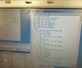
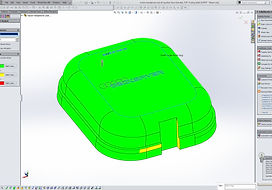
Using the model i created on solidworks i created two tools to form around. This tools where made so that when formed the finished forming sould be the exact same dimensions of what was designed in solidworks. The coordinates of the tools are saved onto a .txt and then added into the cnc computer. You then check the coordinates and change them if need be which is most likly the case. The maching then cuts out the tools starting from the underneith cutting the holes out for the air to pass through from the vacuum. Then you have to turn it over and let the machine route and cut out the overall shape and form of the tool. The image full of colour is showing the draft analysis as the tools cannot have vertically flat side they must have a little draft on if they are any parts that the software think could be wrong or cannot work on the design when forming it comes up in red, there is no red so its ok to start cncing the tool.


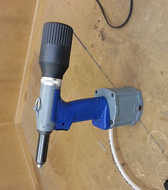
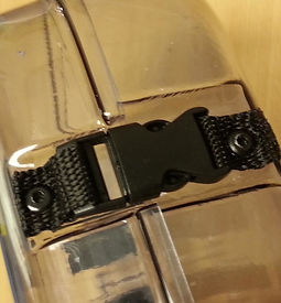
I then cut the 15mm webbing to the correct size i wanted. Originally i just cut the webbing with scissors, this left a scruffy finish on the webbing as you can see above. So i used a blowtorch to heat up the scissor blades and it cut through the webbing leaving a cleaner finish. I also used this techique to put the hole through the webbing for the rivets to go through. I then used a rivet gun to fasten the webbing securly to the case.

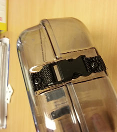
I repeated the process again several times until the back was all connected. I then repeated this process for the front ensuring that the side release clips were accessable and not between the ridges.

There was a couple of problems that occured while manufacturing my prototype model. The biggest problem was that one half was either bigger or small than the other meaning that it was not a flush and snug fit in the coming together of both halfs. This meant that if pressure was applied the top half would slip over the side of the bottom half. This is because one of the tools size needs increasing to ensure there is a better fit as the top is currently overhanging the bottom by around 3mm in both length and width ways. THis may be because there was an error while modelling out the tool or when the case has been formed the material has thinned out when the material is stretch over the tool. to over come this i would look at the tool models and ensure they are both the correct size and if that didnt work then make one side bigger to ensure it fits.
Another problem i faced was the fastening on the front. The side release buckle is idea for what it is used for but the release buttons have ristricted access and are difficult to press because the width of the grooves are not big enough and the sides block the buttons. To over come this i can eiter make the buttons accessable by increasing the width or using a push release button which acts the same as a side release buckle except the button to release the buckle is on the front rather than the side which would be easily accessable. Also connecting the buckle together is not as easy as it hould be, To over come this instead of webbing connecting the buckle to the case it will be an elasticate strip which enable you to fasten the buckle moe easily but still hold the case together and it the goes back to its smaller length when connected together.
Another problem was having the right length of webbing to both hold the half together tight when closed but still be able to easily open the case. My first attempt was rather spot on i must say with it holding the halfs together securly but still allowing you to open and shut it fairy easy but one user that i asked to test the model said it could be abit more slacker. I then made another model and drilled the holes for the rivets on the case in the same place but drilled the holes on the webbing for the rivets another 10mm apart. This did not have a better outcome as there was too much slack in the webbing and the half when fastened where not secure. This would be over come when manufacturing the product for real by testing for the right distances and than having the webbing manufactured especially to fit and have the holes in the case drilled by a cnc to ensure the correct place is drilled time and time again.
With there being 2 indentations into the outside of the case where the webbing strips are attached at the back, this has took up around 10mm of space meaning the headphones need to be pushed in rather than being placed in. I will need to develop this in order to over come this problem this may mean removing the indentation or placing them ruther appart as the top of the headphones would the fit in between the 2 indentations.


From my testing of the attaching componets it is evident that they need to be changes made regarding the fastening of the box and the mechanism to allow it to open and shut freely. The front release buckle will not cut it for my product and the webbing rivet to the back makes the case harder to open and shut as i would like as there is alot of movement in the webbing which makes it hard to shut correcly in place. With this in mind i had a rethink about how i could replace these components and mocked a model up of how the new choosen fastening would work and preform.


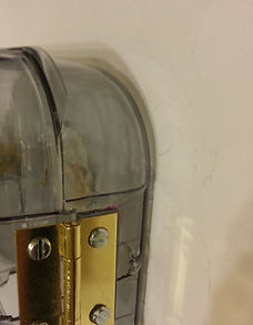
Firstly i cut the middle lip off of the back of the case in order for the back to be flush so that a hinge could be attached in place. i then driiled hole in the polycarbonate and attached the hinge to the back of both halfs of the case. This is not what the hinges will look like on the final product the point of this model was to see if my new desing of the connectors would work more efficiently and easily than the previous attempt.


I did come across some problems though as i had to pack the hinge out on the bottom half with a piece of 3mm polycarbonate in order for the hinge to be flush on both halfs for a fully working hinge. On the final concept there will be no indentation for the hinge to sit in as it is not needed and the back face ideally need to be flush. Also the indentation on the back takes up around 10mm of space which makes the case smaller than expected causing the headphones to be a little bit cramped when you put them in so removing this will also free up 10mm of room to allow the headphone to fit in freely.The second problem was that the lip on the top half which stops the case from puching together was pushing on the bottom half which only allowed me to open the case to half way. It did this as if you pushed it any further than half way it would put stress on the plastic where the hinge is attached as you can see in the picture above right.


i then marked off where i believed the lip should be cut in order for the case to open freely. I then cut the lip off but leaving a nice finish to the lip along the way rather than cutting it straight down i gave it some character and had the lip gradually tapering off.

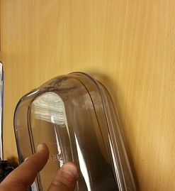
By cutting the lip off this allowed me to open the case fully with both faces of the case touching the surface it was on without putting any stress on the plastic and fixings. By having an hinge on the case this will also make it stronger and not allow the two halfs of the case to close together further than they should as seen above with my hand forcing the halfs together.


I then drilled holes and attached the toggle latch to the front of the model to ensure it will give it a secure lock when the case is closed. I made 1 mistake when attaching the latch as i did not pull the toggl and latch further enough apart so when it is locked it is not a tight as hoped but if the latch and toggle was put on correctly this would make the case more easily accsesable.
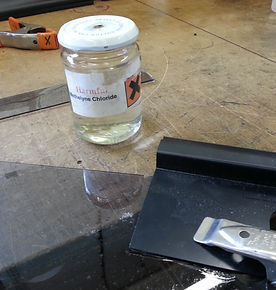

I did testing on how i was going to attach the hinge and toogle latch onto the case. As on the final product both the hinge and catch would both be plastic i decided the best way to attached them to the case would be to use methylene chloride or otherwise known as Dichloromethane. This chemical reacts with the plastic causing it to melt and when both surfaces of the plastic have melted they bond together almost causing a weld like join. The image above and left shows the plastic melted when i pulled the pieces apart around 10 seconds after applying the methylene chloride and once the bond is fully set it is virtually impossible to pull them apart even when you try you hardest. By using this it would make the product look better as there would be no screw or bolts showing and would give the correct strength needed in order for the case to stay together.